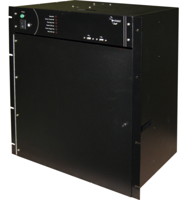
Director DII DFR DDR
- Transient Fault Recording and Analysis
- Long Term Disturbance Recording
- Continuous Waveform Recording
- Continuous Phasor Recording
- Power Quality Monitoring
- E-MAX Display/Analysis Software included
- Sampled Data Streaming Compliant
- IEEE - C37.118-2005
- IEC 61850
- NERC Compliant
- NERC - PRC-002-2
- IEEE C37.232
Director DII DFR DDR
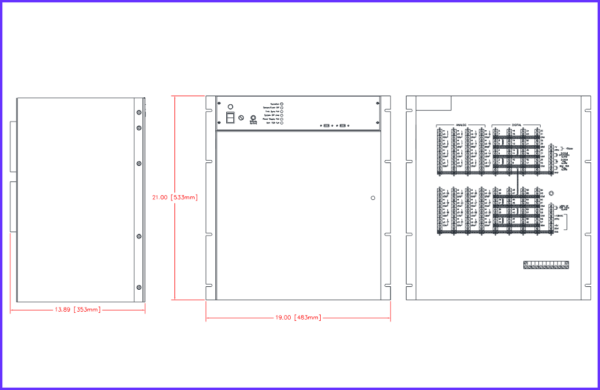
Using the Microsoft Windows 10® operating system, DII features complete Transient and Long-Term Phasor Data Recording, Analysis, and Transmission. E-MAX DII has a maximum capacity of 128 Analog and 256 Digital directly connected channels.
The networking capabilities of DII combined with Windows 10® provides the power and capacity to monitor and collect data from other substation equipment. The TCP/IP addressing and data handling also allow communications with a Master Station and other devices. The DII system includes complete remote control of both the DII and any connected E-MAX DFRs.
Sensors
Software triggers (sensors) are standard for E-MAX Director DII DFRs. Each DFR locally stores the trigger information. All trigger information is user-settable — locally or remotely.
Analog Sensors: Over-, Under- limit and rate software sensors on each channel
Symmetrical component, harmonic, frequency, swing and power sensors.
Operation Limiters Individual Channel: Software Settable up to 15 minutes per fault
Event Sensors: Trigger on ALARM (operate) and/or RTN (return-to-normal) for each channel.
Processing of Record Data
The DII Recording System continuously monitors all channels. If triggered, the DII will record data to memory and process according to user settings. This System automatically identifies fault type and calculates distance to fault. All E-MAX DFR systems can print, display, transmit and e-mail recorded and calculated data automatically or upon operator request. Conversion of record data to COMTRADE and PQDIF formats may be done automatically or upon operator request.
| Analog Inputs | 8 to 128 Inputs |
| Analog Input Range | Voltage: 0 to 500 Vac rms or Current: 0 to 200 Amp |
| Accuracy | Better than 0.1% of full scale |
| Analog Isolation | 2500 Volts rms Channel to Channel and Channel to Ground |
| Maximum Sampling Rate | 15,360 samples/channel/second (256 samples/cycle) |
| Standard Base Sample Rate | 5760 samples/channel/second |
| Digital/Event Inputs | 16 to 256 Inputs |
| 1. Input Configuration | N.O. or N.C. (Software Selected) |
| 2. Input Voltage | 125 Vdc Nominal standard —24, 48, 250 Vdc available |
| 3. Isolation | 2500 VDC (To Ground) and between inputs |
| 4. Resolution | 1/Analog Sample Rate |
| Sensors | |
| 1. Analog Sensors | Over-, Under- limits and rate software sensors on each channel Symmetrical component, harmonic, frequency swing sensors |
| 2. Operation Limiters | Individual Channel: Software Settable up to 15 minutes per fault |
| 3. Event Sensors | Individual Programmable (N.O., N.C., Trigger on ALARM and/or RETURN) |
| 4. External Sensors | Contact or voltage input |
| Continuous Recording | Complies with NERC PRC-002-2 and IEEE C37.232. Default: Records up to 10 Days. |
| Long term Recording | Phasor recording - simultaneous with Transient recording |
| Sample rate is software selectable: 1 sample/cycle, 1/2 sample/cycle, 1/4 sample/cycle, 1/8 sample/cycle | |
| Programmable Record Length - 90 days maximum length | |
| Logs of signals, power and frequency | |
| High Speed Transient Recording | |
| Prefault Period | Up to 99 cycles. Default setting: 10 cycles |
| Postfault Period | Up to 999 cycles. Default setting: 12 cycles |
| Record Storage | Nonvolatile data storage on local SATA drive |
| Resolution | 16 bit |
| Power Supply | DC/DC Converter: 90 - 320 Vdc / 120 Vac. 28-48 Vdc and 250 Vdc Available Current Limited / Overvoltage protected |
| Controller | Intel Quad Core 64 bit CPU. 8 Gb RAM standard |
| 1 USB 3.0 Port, 5 USB 2.0 Ports, Gb Ethernet Port | |
| Graphic Output | Supports color inkjet, laser or dot matrix printers |
| Graphics display on optional monitor | |
| Data Storage | 500 Gb or larger SATA Solid State Drive |
| Clock Options | GPS Timing - IRIG B Decoder Internal (1 kHz or TTL), External GPS Clock |
| Accuracy | Better than 20 µs |
| Communications Capability | |
| 1. To Master Stations | Transfer of data files through Windows FTP Service |
| Functions with multiple-Master system | |
| Windows Remote Desktop for Remote Control | |
| 2. Email | Automatic reporting to multiple user selected email addresses |
| 3. LAN and WAN | Software supports communication via TCP/IP |
| Software Supplied | |
| 1. Master Station & Recorder | Microsoft Windows 10® |
| Complete remote control, test and data retrieval, display and screen manipulation | |
| Remote setting of program and system parameters | |
| Remote setting of program and system parameters | |
| 2. Display/Analysis Software | E-MAX WinGrafDisp (Waveform Data) |
| E-MAX Phasorview (Phasor Data) | |
| Environmental Characteristics | |
| Operating Temperature | 0 To 60 degrees C |
| Storage | -20 to 65 degrees C |
| Relative Humidity | 0 to 95% R.H. non-condensing |
| Surge Withstand Capability | ANSI C37.90.1 1989 |
| International Standards Compliance | |
| Safety | IEC 60255-2 IEC 60255-4 IEC 60255-5 |
| Immunity | IEC 61000-4-2 IEC 61000-4-3 IEC 61000-4-4 IEC 61000-4-6 |
 E-MAX Instruments

