CM, CMD Circuit Monitor
* denotes UL recognized models.
| Part Number | Model | Nominal | Minimum | Nominal Resistance |
| 632A501 * | CM | 125 Vdc | 90 V | 15 K |
| 632A502 * | CM | 48 Vdc | 30 V | 6.5 K |
| 632A503 * | CM | 250Vdc | 175 V | 35 K |
| 632A418 * | CM | 170 Vdc | 130 V | 21 K |
| 632A504 * | CMD | 125 Vdc | 90 V | 15 K |
| 632A505 * | CMD | 48 Vdc | 30 V | 6.5 K |
| 632A506 * | CMD | 250 Vdc | 175 V | 35 K |
| 632A419 * | CMD | 170 Vdc | 130 V | 21 K |
| Circuit Monitors | without | LEDs | ||
| 632A514 * | CMD | 125 Vdc | 90 V | 15 K |
| 632A515 * | CMD | 48 Vdc | 30 V | 6.5 K |
| LED Indicator | ||||
| 632A401 | LED Assembly | 125 Vdc | ||
| 632A402 | LED Assembly | 48 Vdc | ||
| 632A403 | LED Assembly | 120 Vac | ||
| 632A404 | LED Assembly | 250 Vac |
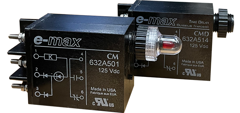
CM, CMD Circuit Monitor
- Continuous monitoring of trip coil continuity
- LED indication of open trip circuits
- N.O. or N.C. contact for remote indication of open trip coils.
- Self-monitoring — long-life
- Can also be used as a self-latching, high speed target for trip indication
- UL Recognized
- RoHS Compliant (Directive 2002/95/EC)
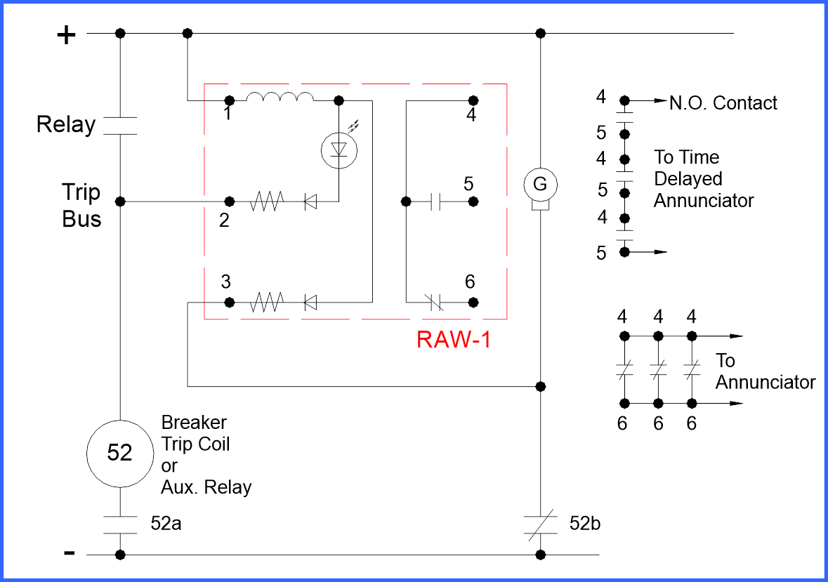
The RAW-1 and the CM are panel mounted relays containing a series LED for visual indication and blocking diodes for prevention of alarm indication when the breaker is opened. If a trip coil or auxiliary trip relay coil opens, the LED goes out and the relay is deenergized. The relay itself is self-monitoring since opening of any of the series components causes the same conditions as the loss of the trip coil. On breaker opening, the RAW-1 is energized through the breaker “B” contact. The time delay auxiliary relay does not time out.
The CM acts as a continuous monitor of the breaker position and the trip coil.
The RAW-1 is connected to supply monitoring through indication and alarm contacts for security. When a remote alarm is received, the unlit LED identifies the open circuit. Loss of the trip bus voltage is also signaled by a contact operation.
The RAW-1D and the CMD contain the additional feature of delayed drop-out. The delay of approximately 200 milliseconds is designed to allow auxiliary contacts to transfer.
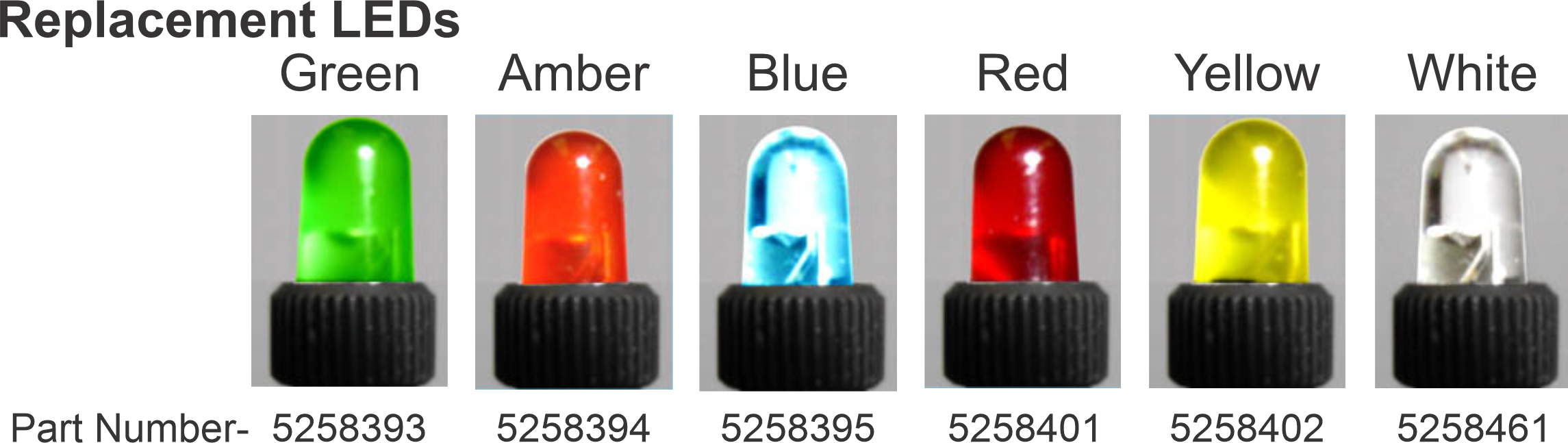
The RAW-1, RAW -1D, CM and CMD are designed with auxiliary resistors and diodes for easy addition to existing installations. The output contact is a one form C. All units come with a red LED as standard. Amber, green, blue, white and yellow LEDs are also available.
The LED is plug-in replaceable and has a life of over 100,000 hours. The LED is protected against accidental reverse polarity application by a diode.
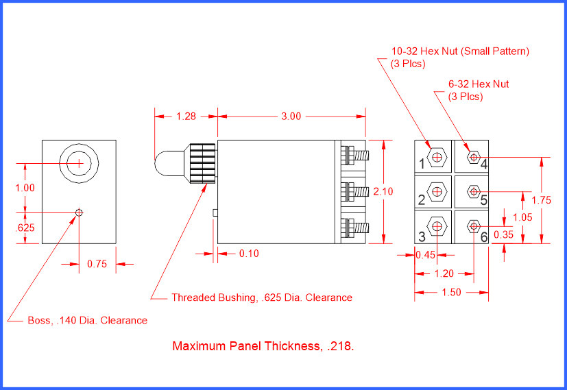
To ease panel layout, E-MAX designed the LED Indicator Assembly. Housed in the same chassis as the RAW and CM series relays, the Assembly functions as a simple indicator lamp. The LED Indicator Assembly is available for 125 Vdc, 48 Vdc, 250 Vdc, and 120 Vac input. Like the RAW and CM relays, the LED Indicator Assembly comes with red as the default LED color. Amber, green, blue, white and yellow LED’s may be substituted.
- Isolation 1500 Vdc minimum contact to coil or coil to ground.
- Contact Rating Switching - 50 Watts 1.5 A max.; 500 V max. Carrying - 3.2 A max.
- Operating Temperature -25 to 650 C
- Storage Temperature -54 to 850 C
- Altitude 0 - 50,000 feet
- Life Expectancy 1 x 10⁵ Operations
- Vibration Insensitive to Vibration below 1 Khz
- Noise Immunity ANSI C37.90a-1974
- Cycling Rate 60 cps Maximum
When ordering specify Part Number and LED color. Example 632A301-Yellow
Default LED color: Red
Standard Colors available: Amber, Yellow, Green, Blue, White
Note: The blue LED appears clear when not illuminated.
* UL Certificate Number - NKCR2.E322922 For Canada - NKCR8.E322922
E-MAX Circuit Monitors are RoHS Compliant
The substances banned under RoHS are lead (Pb), mercury (Hg), cadmium (Cd), hexavalent chromium (CrVI), polybrominated biphenyls (PBB) and polybrominated diphenyl ethers (PBDE).